Triplanar Mapping
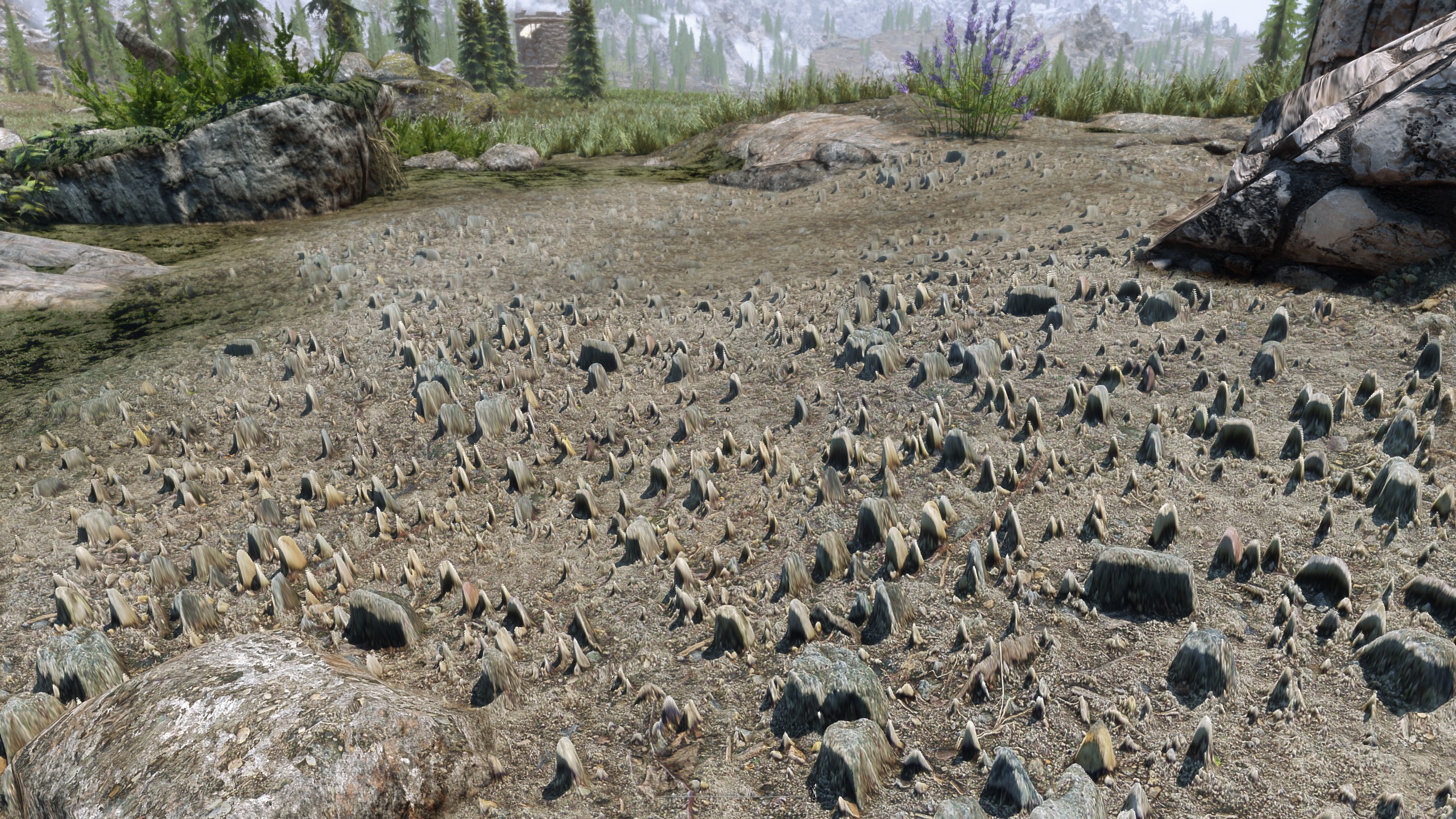
Triplanar mapping is a texture mapping technique used to eliminate distortion and stretching. The usual way to map textures is to pass the mesh’s UV coordinates to a shader and sample textures using those coordinates. However, in some cases, these UV coordinates can cause textures to look distorted, as shown in the example below.

Distorted Terrain Textures. WizardPie42 from Reddit.
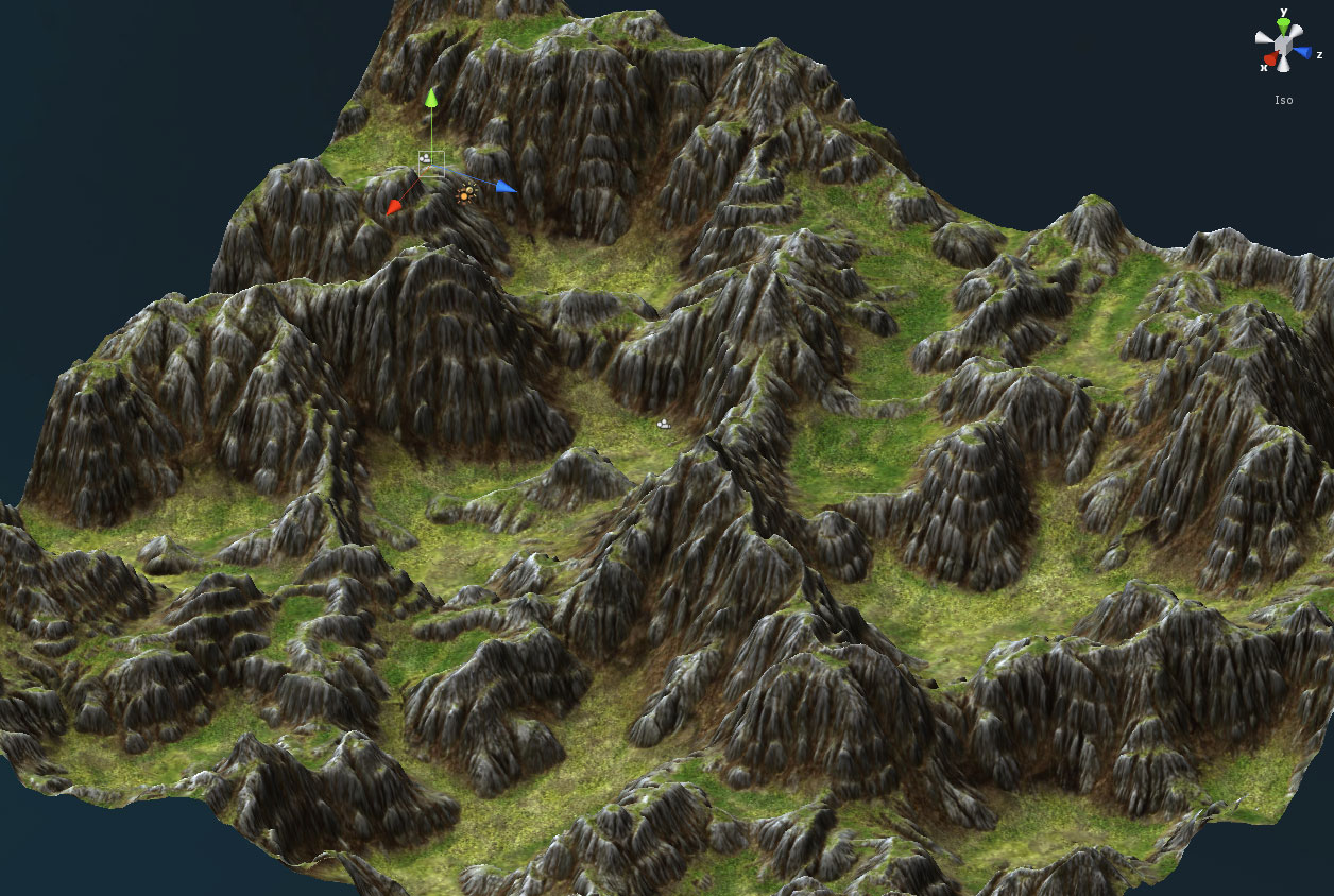
Triplanar mapping overcomes this limitation by mapping multiple 2D textures projected onto the surface along the X, Y and Z axes. The surface is divided into 3 different regions and each is textured using its corresponding 2D projection. For each point, the influence of the 3 mapped textures are calculated with blend weights. For example, if the surface normal is almost parallel to the Y axis, the sample from the Y-projected plane will have the greatest influence. This technique shows great results when rendering terrains, because distortion caused by complex surface geometry is mitigated and textures from different regions can be seamlessly blended.

Triplanar Mapping on Terrains

Comparison of UV Mapping (left) and Triplanar Mapping (right). Brent Owens.
However, there are drawbacks to this technique. Since triplanar mapping blends 3 different textures, there may be certain points or perspectives where the texture appears blurred. Also, because this technique uses world space coordinates instead of UVs, the tangents will not be correct. Normals from normal maps will be incorrect as well. Despite blending 3 textures, seams can be visible in certain occasions too, all of which results in loss of detail. There are approaches like blending with a depth map to create more realistic results. There is a link in the reference section for a more detailed description.
Performance is also an issue. Triplanar mapping may not be as efficient as traditional texture mapping in most cases since it maps the same texture 3 times. So for simple geometry, it may be a better option to sample with UVs. Moreover, if there are multiple textures to sample like normal maps, specular maps, ambient occlusion maps etc; performance should be carefully measured to use this technique in production.
Implementation
Here’s a simple implementation of triplanar mapping in Unity.
Shader "Custom/Triplanar"
{
    Properties
    {
        _MainTex ("Texture", 2D) = "white" {}

        [KeywordEnum(XY, XZ, YZ, Triplanar)] _MappingPlane ("Mapping Plane", Float) = 1
        _BlendSharpness("Blend Sharpness", Range(0, 5)) = 1.0
    }
    SubShader
    {
        Tags {
            "RenderPipeline"="UniversalPipeline"
            "RenderType"="Opaque"
            "Queue"="Geometry"
        }

        Pass
        {
            Name "Universal Forward"
            Tags {"LightMode" = "UniversalForward" }

            HLSLPROGRAM
            #pragma prefer_hlslcc gles
            #pragma exclude_renderers d3d11_9x

            #pragma vertex vert
            #pragma fragment frag

            #pragma shader_feature _MAPPINGPLANE_XY _MAPPINGPLANE_XZ _MAPPINGPLANE_YZ _MAPPINGPLANE_TRIPLANAR

            #include "Packages/com.unity.render-pipelines.universal/ShaderLibrary/Lighting.hlsl"

            struct VertexInput
            {
                float4 vertex: POSITION;
                float3 normal: NORMAL;
                float2 uv : TEXCOORD0;
            };

            struct VertexOutput
            {
                float4 vertex : SV_POSITION;
                float2 uv : TEXCOORD0;
                float3 worldPos : TEXCOORD2;
                float3 worldNormal: TEXCOORD3;
            };

            Texture2D _MainTex;
            SamplerState sampler_MainTex;
            float _BlendSharpness;

            VertexOutput vert(VertexInput v)
            {
                VertexOutput o;
                o.vertex = TransformObjectToHClip(v.vertex.xyz);
                o.uv = v.uv;
                o.worldPos = TransformObjectToWorld(v.vertex.xyz);
                o.worldNormal = TransformObjectToWorldNormal(v.normal);
                return o;
            }

            half4 frag(VertexOutput i): SV_Target
            {
                // color to return
                half4 color = half4(0,0,0,1);

                #if defined(_MAPPINGPLANE_XY)
                color = _MainTex.Sample(sampler_MainTex, i.worldPos.xy);

                #elif defined(_MAPPINGPLANE_XZ)
                color = _MainTex.Sample(sampler_MainTex, i.worldPos.xz);

                #elif defined(_MAPPINGPLANE_YZ)
                color = _MainTex.Sample(sampler_MainTex, i.worldPos.yz);

                #elif defined(_MAPPINGPLANE_TRIPLANAR)
                // sample for each projection plane
                half3 xAlbedo = _MainTex.Sample(sampler_MainTex, i.worldPos.yz);
                half3 yAlbedo = _MainTex.Sample(sampler_MainTex, i.worldPos.xz);
                half3 zAlbedo = _MainTex.Sample(sampler_MainTex, i.worldPos.xy);

                // calculate weights and normalize
                half3 weight = pow(abs(i.worldNormal), _BlendSharpness);
                weight /= weight.x + weight.y + weight.z;

                // blend colors
                color.rgb = xAlbedo * weight.x + yAlbedo * weight.y + zAlbedo * weight.z;
                #endif

                return color;
            }
            ENDHLSL
        }
    }
}
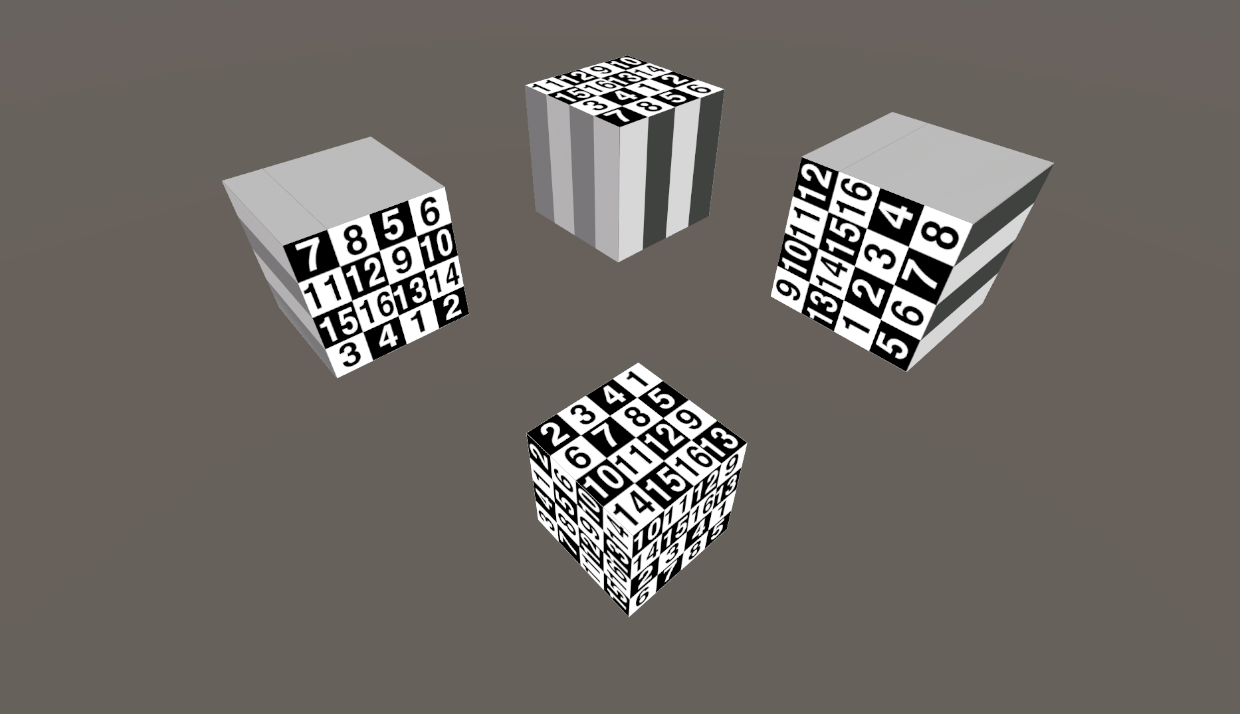
Here’s what it looks like when applying the above shader to a cube. The top 3 cubes are each mapped to the 3 projection planes and the cube at the bottom is triplanar mapped.

Mapping on XY, XZ, YZ Plane and Triplanar Mapping.
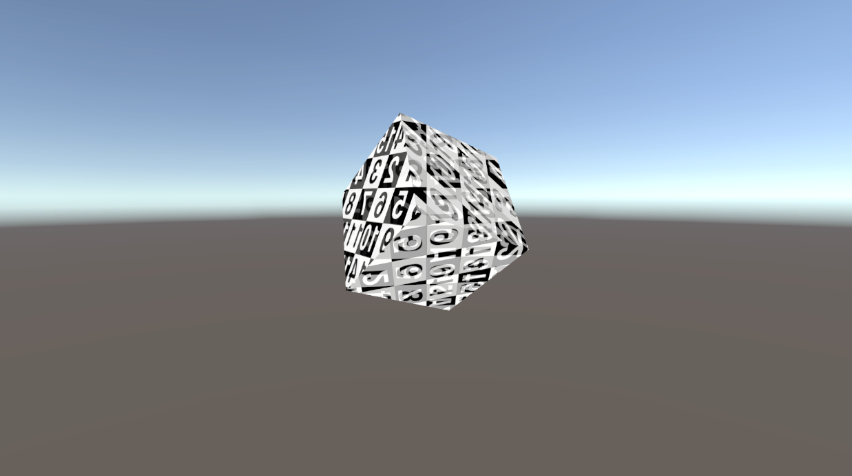
As mentioned above, blend artifacts may be visible from certain angles even if _BlendSharpness is set to a high value. Below is an example of when blending is visible on the mesh.

Blur Artifact
Adding additional code to this shader, such as depth based blending, sampling textures on more than 3 projective planes, or altering the blending method, can extend the triplanar shader across various use cases. Refer to the resources listed in the References section below for more comprehensive explanations and implementations.
References
Triplanar Mapped Terrain by James O’Hare
Advanced Terrain Texture Splatting by Andrey Mishkinis
Use Tri-Planar Texture Mapping for Better Terrain by Brent Owens
Normal Mapping for a Triplanar Shader by Ben Golus
